6:41 PM ISO/OSI Network Model |
It is the standard model for networking protocols and distributed applications proposed by the International Standard Organization. Open System Interconnect (ISO/OSI) model, as the name says: its is open for all. It defines seven network layers.
 Below are the layers and their function:
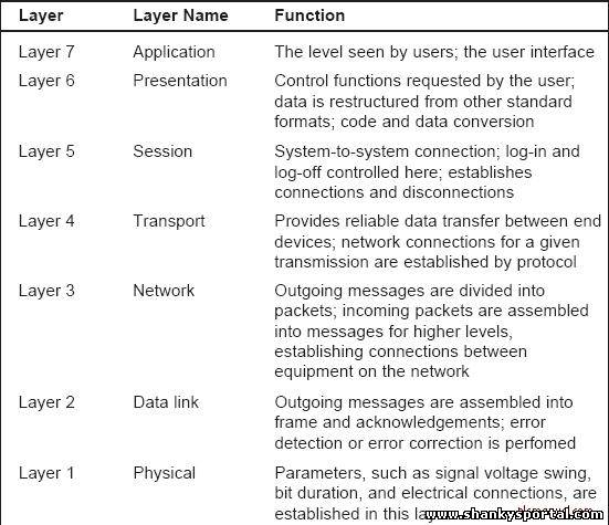 More detailed description of layers with their function:
Layer 1 - Physical
Physical layer defines the cable or physical medium itself, e.g., thinnet, thicknet, unshielded twisted pairs (UTP). All media are functionally equivalent. The main difference is in convenience and cost of installation and maintenance. Converters from one media to another operate at this level. Layer 2 - Data Link Data Link layer defines the format of data on the network. A network data frame, aka packet, includes checksum, source and destination address, and data. The largest packet that can be sent through a data link layer defines the Maximum Transmission Unit (MTU). The data link layer handles the physical and logical connections to the packet's destination, using a network interface. A host connected to an Ethernet would have an Ethernet interface to handle connections to the outside world, and a loopback interface to send packets to itself. Ethernet addresses a host using a unique, 48-bit address called its Ethernet address or Media Access Control (MAC) address. MAC addresses are usually represented as six colon-separated pairs of hex digits, e.g., 8:0:20:11:ac:85. This number is unique and is associated with a particular Ethernet device. Hosts with multiple network interfaces should use the same MAC address on each. The data link layer's protocol-specific header specifies the MAC address of the packet's source and destination. When a packet is sent to all hosts (broadcast), a special MAC address (ff:ff:ff:ff:ff:ff) is used. Layer 3 - Network NFS uses Internetwork Protocol (IP) as its network layer interface. IP is responsible for routing, directing datagrams from one network to another. The network layer may have to break large datagrams, larger than MTU, into smaller packets and host receiving the packet will have to reassemble the fragmented datagram. The Internetwork Protocol identifies each host with a 32-bit IP address. IP addresses are written as four dot-separated decimal numbers between 0 and 255, e.g., 129.79.16.40. The leading 1-3 bytes of the IP identify the network and the remaining bytes identifies the host on that network. The network portion of the IP is assigned by InterNIC Registration Services, under the contract to the National Science Foundation, and the host portion of the IP is assigned by the local network administrators, locally by noc@indiana.edu. For large sites, usually subnetted like ours, the first two bytes represents the network portion of the IP, and the third and fourth bytes identify the subnet and host respectively. Even though IP packets are addressed using IP addresses, hardware addresses must be used to actually transport data from one host to another. The Address Resolution Protocol (ARP) is used to map the IP address to it hardware address. Layer 4 - Transport Transport layer subdivides user-buffer into network-buffer sized datagrams and enforces desired transmission control. Two transport protocols, Transmission Control Protocol (TCP) and User Datagram Protocol (UDP), sits at the transport layer. Reliability and speed are the primary difference between these two protocols. TCP establishes connections between two hosts on the network through 'sockets' which are determined by the IP address and port number. TCP keeps track of the packet delivery order and the packets that must be resent. Maintaining this information for each connection makes TCP a stateful protocol. UDP on the other hand provides a low overhead transmission service, but with less error checking. NFS is built on top of UDP because of its speed and statelessness. Statelessness simplifies the crash recovery. Layer 5 - Session The session protocol defines the format of the data sent over the connections. The NFS uses the Remote Procedure Call (RPC) for its session protocol. RPC may be built on either TCP or UDP. Login sessions uses TCP whereas NFS and broadcast use UDP. Layer 6 - Presentation External Data Representation (XDR) sits at the presentation level. It converts local representation of data to its canonical form and vice versa. The canonical uses a standard byte ordering and structure packing convention, independent of the host. Layer 7 - Application Provides network services to the end-users. Mail, ftp, telnet, DNS, NIS, NFS are examples of network applications. TCP/IP Network Model Although the OSI model is widely used and often cited as the standard, TCP/IP protocol has been used by most Unix workstation vendors. TCP/IP is designed around a simple four-layer scheme. It does omit some features found under the OSI model. Also it combines the features of some adjacent OSI layers and splits other layers apart. The four network layers defined by TCP/IP model are as follows. Layer 1 - Data Link This layer defines the network hardware and device drivers. Layer 2 - Network This layer is used for basic communication, addressing and routing. TCP/IP uses IP and ICMP protocols at the network layer. Layer 3 - Transport Handles communication among programs on a network. TCP and UDP falls within this layer. Layer 4 - Application End-user applications reside at this layer. Commonly used applications include NFS, DNS, arp, rlogin, talk, ftp, ntp and traceroute. |
|
|
Related blogs
You may also like to see:
| [2014-02-06] | [Technical Solution] |
| | |
| [2014-01-29] | [Technical Solution] |
| | |
| [2014-03-09] | [Technical Solution] |
| | |
| [2015-01-05] | [Technical Solution] |
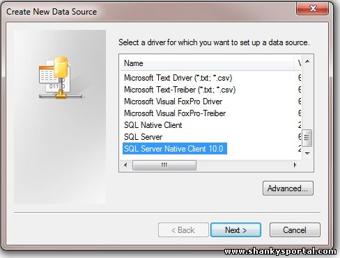 How to create ODBC data source and drivers to connect to Oracle or sql server database How to create ODBC data source and drivers to connect to Oracle or sql server database | |
| [2015-02-09] | [Technical Solution] |
 Soving Rubik's Cube Second layer: Layered approach by Shanky Soving Rubik's Cube Second layer: Layered approach by Shanky | |
| Total comments: 0 | |